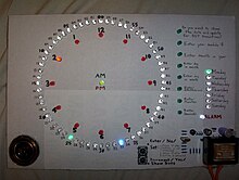


Charlieplexing (also known as tristate multiplexing, reduced pin-count LED multiplexing, complementary LED drive and crossplexing) is a technique for accessing a large number of LEDs, switches, micro-capacitors or other I/O entities, using relatively few tri-state logic wires from a microcontroller. These I/O entities can be wired as discrete components,[1][2] x/y arrays,[3][4] or woven in a diagonally intersecting pattern to form diagonal arrays.[5]
The simplest way to address a single pixel (or input button) is to run a wire out to it and another wire back to ground, but this requires a lot of wiring. A slight improvement is to have everything return on a common ground, but this still requires one wire (and one pin on the microcontroller) for each pixel or button. For an X by Y array, X*Y pins are required.
With tri-state logic pins (high, low, disconnected), matrix wiring needs only X+Y pins and wires. Each X and each Y take turns being on vs being disconnected; the disadvantage is that each light is only powered at most 1/(X*Y) of the time. If there is enough Fan-out, the Y pins can be left always on, and all checked in parallel. The refresh can then happen every 1/X of the time, but the X wires each need to pass enough current to light up Y lights at once.
Charlieplexing is a further improvement on matrix wiring. Instead of X horizontal wires meeting Y vertical wires, every wire meets every other wire. Assuming diodes are used for the connections (to distinguish between wire 3 meeting wire 5 vs wire 5 meeting wire 3), Charlieplexing needs only about half as many pins as a conventional matrix arrangement, at the cost of more complicated mapping. Alternatively, the same number of pins will support a display nearly four times (doubling in both directions) as large.
This enables these I/O entities (LEDs, switches etc.) to be connected between any two microcontroller I/Os - e.g. with 4 I/Os, each I/O can pair with 3 other I/Os, resulting in 6 unique pairings (1/2, 1/3, 1/4, 2/3, 2/4, 3/4). Only 4 pairings are possible with standard x/y multiplexing (1/3, 1/4, 2/3, 2/4). Also, due to the microcontroller's ability to reverse the polarity of the 6 I/O pairs, the number of LEDS (or diodes) that are uniquely addressable, can be doubled to 12 - adding LEDS 2/1, 3/1, 4/1, 3/2, 4/2 and 4/3.
Although it is more efficient in its use of I/O, a small amount of address manipulation is required when trying to fit Charlieplexing into a standard x/y array.
Other issues that affect standard multiplexing but are exacerbated by Charlieplexing are:
- consideration of current requirements and the forward voltages of the LEDs.
- a requirement to cycle through the in-use LEDs rapidly so that the persistence of the human eye perceives the display to be lit as a whole. Multiplexing can generally be seen by a strobing effect and skewing if the eye's focal point is moved past the display rapidly.
- ^ "Charlieplexing made easy". Retrieved 2024-01-08.
- ^ "Charlieplexed-Arduino-8x8-LED-Grid-Display". Retrieved 2024-01-08.
- ^ "Making Charlieplex arrays". Retrieved 2024-01-08.
- ^ "sparkfun-led-array-8x7-hookup-guide". Retrieved 2024-01-09.
- ^ "Touch sensor". Retrieved 2024-01-08.