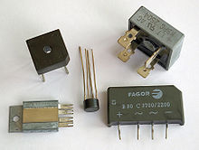
 Diode bridge in various packages | |
| Type | Semiconductor |
|---|---|
| Invented | Karol Pollak in 1895 |
| Electronic symbol | |
 2 alternating-current (AC) inputs converted into 2 direct-current (DC) outputs | |

A diode bridge is a bridge rectifier circuit of four diodes that is used in the process of converting alternating current (AC) from the input terminals to direct current (DC, i.e. fixed polarity) on the output terminals. Its function is to convert the negative voltage portions of the AC waveform to positive voltage, after which a low-pass filter can be used to smooth the result into DC.[1]
When used in its most common application, for conversion of an alternating-current (AC) input into a direct-current (DC) output, it is known as a bridge rectifier. A bridge rectifier provides full-wave rectification from a two-wire AC input, resulting in lower cost and weight as compared to a rectifier with a three-wire input from a transformer with a center-tapped secondary winding.[2]
Prior to the availability of integrated circuits, a bridge rectifier was constructed from separate diodes. Since about 1950, a single four-terminal component containing the four diodes connected in a bridge configuration has been available and is now available with various voltage and current ratings.
Diodes are also used in bridge topologies along with capacitors as voltage multipliers.
- ^ Yazdani, Amirnaser; Iravani, Reza (15 February 2010). Voltage-Sourced Converters in Power Systems Modeling, Control, and Applications. Willey. ISBN 9780470521564.
- ^ Horowitz, Paul; Hill, Winfield (1989). The Art of Electronics (Second ed.). Cambridge University Press. pp. 44–47. ISBN 0-521-37095-7.