This article may be too long to read and navigate comfortably. When this tag was added, its readable prose size was 18,000 words. (June 2023) |


- Three electron emitters (for red, green, and blue phosphor dots)
- Electron Beams and Electron Guns
- Focusing coils
- Deflection coils
- Connection for final anodes (referred to as the "ultor"[1] in some receiving tube manuals)
- Mask for separating beams for red, green, and blue part of the displayed image
- Phosphor layer (screen) with red, green, and blue zones
- Close-up of the phosphor-coated inner side of the screen

- Deflection coils
- Electron Beam and Electron Gun
- Focusing coil
- Phosphor layer on the inner side of the screen; emits light when struck by the electron beam
- Filament for heating the cathode
- Graphite layer on the inner side of the tube
- Rubber or silicone gasket where the anode voltage wire enters the tube (anode cup)
- Cathode
- Air-tight glass body of the tube
- Screen
- Coils in yoke
- Control electrode regulating the intensity of the electron beam and thereby the light emitted from the phosphor
- Contact pins for cathode, filament and control electrode
- Wire for anode high voltage
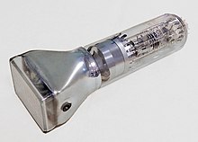
A cathode-ray tube (CRT) is a vacuum tube containing one or more electron guns, which emit electron beams that are manipulated to display images on a phosphorescent screen.[2] The images may represent electrical waveforms on an oscilloscope, a frame of video on an analog television set (TV), digital raster graphics on a computer monitor, or other phenomena like radar targets. A CRT in a TV is commonly called a picture tube. CRTs have also been used as memory devices, in which case the screen is not intended to be visible to an observer. The term cathode ray was used to describe electron beams when they were first discovered, before it was understood that what was emitted from the cathode was a beam of electrons.
In CRT TVs and computer monitors, the entire front area of the tube is scanned repeatedly and systematically in a fixed pattern called a raster. In color devices, an image is produced by controlling the intensity of each of three electron beams, one for each additive primary color (red, green, and blue) with a video signal as a reference.[3] In modern CRT monitors and TVs the beams are bent by magnetic deflection, using a deflection yoke. Electrostatic deflection is commonly used in oscilloscopes.[3]


The tube is a glass envelope which is heavy, fragile, and long from front screen face to rear end. Its interior must be close to a vacuum to prevent the emitted electrons from colliding with air molecules and scattering before they hit the tube's face. Thus, the interior is evacuated to less than a millionth of atmospheric pressure.[4] As such, handling a CRT carries the risk of violent implosion that can hurl glass at great velocity. The face is typically made of thick lead glass or special barium-strontium glass to be shatter-resistant and to block most X-ray emissions. This tube makes up most of the weight of CRT TVs and computer monitors.[5][6]
Since the early 2010s, CRTs have been superseded by flat-panel display technologies such as LCD, plasma display, and OLED displays which are cheaper to manufacture and run, as well as significantly lighter and thinner. Flat-panel displays can also be made in very large sizes whereas 40–45 inches (100–110 cm) was about the largest size of a CRT.[7]
A CRT works by electrically heating a tungsten coil[8] which in turn heats a cathode in the rear of the CRT, causing it to emit electrons which are modulated and focused by electrodes. The electrons are steered by deflection coils or plates, and an anode accelerates them towards the phosphor-coated screen, which generates light when hit by the electrons.[9][10][11]
- ^ US 5463290, Fitzgerald, William V., "Power supply stabilization circuit with separate AC/DC negative feedback paths", published 1995-10-31, assigned to Thomson Consumer Electronics Inc.
- ^ "History of the Cathode Ray Tube". About.com. Archived from the original on 9 July 2012. Retrieved 4 October 2009.
- ^ a b "How Computer Monitors Work". 16 June 2000. Retrieved 4 October 2009.
- ^ Sinclair, Ian (1 January 2011), Sinclair, Ian (ed.), "Chapter 8 - Elements of Television", Electronics Simplified (Third Edition), Oxford: Newnes, pp. 137–165, ISBN 978-0-08-097063-9, retrieved 28 December 2023
- ^ Dhir, Ravindra K.; Limbachiya, Mukesh C.; Dyer, Thomas D. (2001). Recycling and Reuse of Glass Cullet: Proceedings of the International Symposium Organised by the Concrete Technology Unit and Held at the University of Dundee, Scotland, UK on 19-20 March 2001. Thomas Telford. ISBN 978-0-7277-2994-1.[page needed]
- ^ Musgraves, J. David; Hu, Juejun; Calvez, Laurent (8 November 2019). "Cathod Ray-Tube Design". Springer Handbook of Glass. Springer Nature. p. 1367. ISBN 978-3-319-93728-1.
- ^ "Folha de S.Paulo - TV de tela grande lidera vendas no país - 27/08/2010". www1.folha.uol.com.br. Retrieved 8 July 2024.
- ^ JP 2003331751, Hasegawa, Yoji, "Cathode-ray tube and its manufacturing method, and electron gun", published 2003-11-21, assigned to Sony Corp.
- ^ "How Computer Monitors Work". HowStuffWorks. 16 June 2000.
- ^ "Cathode Ray Tube (CRT)". Circuit Globe. 6 June 2017.
- ^ "Home Page for ECE 3065 -- Electromagnetic Applications". propagation.ece.gatech.edu.