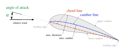


In aeronautics, the chord is an imaginary straight line joining the leading edge and trailing edge of an aerofoil. The chord length is the distance between the trailing edge and the point where the chord intersects the leading edge.[1][2] The point on the leading edge used to define the chord may be the surface point of minimum radius.[2] For a turbine aerofoil the chord may be defined by the line between points where the front and rear of a 2-dimensional blade section would touch a flat surface when laid convex-side up.[3]
The wing, horizontal stabilizer, vertical stabilizer and propeller/rotor blades of an aircraft are all based on aerofoil sections, and the term chord or chord length is also used to describe their width. The chord of a wing, stabilizer and propeller is determined by measuring the distance between leading and trailing edges in the direction of the airflow. (If a wing has a rectangular planform, rather than tapered or swept, then the chord is simply the width of the wing measured in the direction of airflow.) The term chord is also applied to the width of wing flaps, ailerons and rudder on an aircraft.
The term is also applied to compressor and turbine aerofoils in gas turbine engines such as turbojet, turboprop, or turbofan engines for aircraft propulsion.
Many wings are not rectangular, so they have different chords at different positions. Usually, the chord length is greatest where the wing joins the aircraft's fuselage (called the root chord) and decreases along the wing toward the wing's tip (the tip chord). Most jet aircraft use a tapered swept wing design. To provide a characteristic figure that can be compared among various wing shapes, the mean aerodynamic chord (abbreviated MAC) is used, although it is complex to calculate. The mean aerodynamic chord is used for calculating pitching moments.[4]
- ^ L. J. Clancy (1975), Aerodynamics, Section 5.2, Pitman Publishing Limited, London. ISBN 0-273-01120-0
- ^ a b Houghton, E. L.; Carpenter, P.W. (2003). Butterworth Heinmann (ed.). Aerodynamics for Engineering Students (5th ed.). ISBN 0-7506-5111-3. p.18
- ^ https://www.abbottaerospace.com/downloads/nasa-sp-290-turbine-design-and-application/, p.66 [dead link]
- ^ The Design Of The Aeroplane, Darrol Stinton 1984,ISBN 0 632 01877 1, p.26