The optical transfer function (OTF) of an optical system such as a camera, microscope, human eye, or projector specifies how different spatial frequencies are captured or transmitted. It is used by optical engineers to describe how the optics project light from the object or scene onto a photographic film, detector array, retina, screen, or simply the next item in the optical transmission chain. A variant, the modulation transfer function (MTF), neglects phase effects, but is equivalent to the OTF in many situations.
Either transfer function specifies the response to a periodic sine-wave pattern passing through the lens system, as a function of its spatial frequency or period, and its orientation. Formally, the OTF is defined as the Fourier transform of the point spread function (PSF, that is, the impulse response of the optics, the image of a point source). As a Fourier transform, the OTF is complex-valued; but it will be real-valued in the common case of a PSF that is symmetric about its center. The MTF is formally defined as the magnitude (absolute value) of the complex OTF.
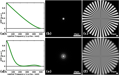
The image on the right shows the optical transfer functions for two different optical systems in panels (a) and (d). The former corresponds to the ideal, diffraction-limited, imaging system with a circular pupil. Its transfer function decreases approximately gradually with spatial frequency until it reaches the diffraction-limit, in this case at 500 cycles per millimeter or a period of 2 μm. Since periodic features as small as this period are captured by this imaging system, it could be said that its resolution is 2 μm.[1] Panel (d) shows an optical system that is out of focus. This leads to a sharp reduction in contrast compared to the diffraction-limited imaging system. It can be seen that the contrast is zero around 250 cycles/mm, or periods of 4 μm. This explains why the images for the out-of-focus system (e,f) are more blurry than those of the diffraction-limited system (b,c). Note that although the out-of-focus system has very low contrast at spatial frequencies around 250 cycles/mm, the contrast at spatial frequencies near the diffraction limit of 500 cycles/mm is diffraction-limited. Close observation of the image in panel (f) shows that the image of the large spoke densities near the center of the spoke target is relatively sharp.
- ^ The exact definition of resolution may vary and is often taken to be 1.22 times larger as defined by the Rayleigh criterion.