This article needs additional citations for verification. (March 2018) |


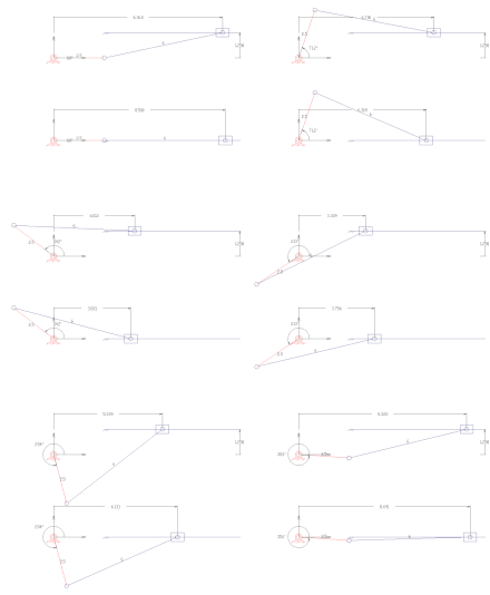
A slider-crank linkage is a four-link mechanism with three revolute joints and one prismatic (sliding) joint.[1] The rotation of the crank drives the linear movement of the slider, or the expansion of gases against a sliding piston in a cylinder can drive the rotation of the crank.
There are two types of slider-cranks: in-line and offset.
- In-line: An in-line slider-crank has its slider positioned so the line of travel of the hinged joint of the slider passes through the base joint of the crank. This creates a symmetric slider movement back and forth as the crank rotates.
- Offset: If the line of travel of the hinged joint of the slider does not pass through the base pivot of the crank, the slider movement is not symmetric. It moves faster in one direction than the other. This is called a quick-return mechanism.
There are also two methods to design each type: graphical and analytical.
- ^ Hartenberg, R.S. & J. Denavit (1964) Kinematic synthesis of linkages, New York: McGraw-Hill, online link from Cornell University.