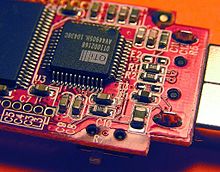


Surface-mount technology (SMT), originally called planar mounting,[1] is a method in which the electrical components are mounted directly onto the surface of a printed circuit board (PCB).[2] An electrical component mounted in this manner is referred to as a surface-mount device (SMD). In industry, this approach has largely replaced the through-hole technology construction method of fitting components, in large part because SMT allows for increased manufacturing automation which reduces cost and improves quality.[3] It also allows for more components to fit on a given area of substrate. Both technologies can be used on the same board, with the through-hole technology often used for components not suitable for surface mounting such as large transformers and heat-sinked power semiconductors.
An SMT component is usually smaller than its through-hole counterpart because it has either smaller leads or no leads at all. It may have short pins or leads of various styles, flat contacts, a matrix of solder balls (BGAs), or terminations on the body of the component.
- ^ Williams, Paul, ed. (1999). Status of the Technology Industry Activities and Action Plan (PDF). Surface Mount Technology. Surface Mount Council. Archived (PDF) from the original on 2015-12-28.
- ^ "Surface Mount Technology - an overview | ScienceDirect Topics". www.sciencedirect.com. Retrieved 2022-09-30.
- ^ Staff, History Computer (2022-05-19). "(SMT) Surface-Mount Technology: Meaning, Definition, and Examples". History-Computer. Retrieved 2022-09-30.